All experienced poultry farmers are well aware that one of the main conditions for successful incubation of eggs, in addition to properly selected temperature and humidity, is their periodic turning over.
And it should be done according to a strictly defined technology. All existing incubators are divided into three groups - automatic, mechanical and manual, and the last two varieties suggest that the process of turning eggs will not be a machine, but a man.
Simplify this task will help the timer, which, with some time and experience, you can do it yourself. Several methods for manufacturing such a device are described below.
What is it needed for
The egg turn-over timer in an incubator is a device that opens and closes an electrical circuit at the same time interval, that is, in simple terms, a primitive relay. Our task is to turn off and then turn on the main nodes of the incubator again, thus automating the system as much as possible and minimizing possible errors caused by the human factor.
The timer, in addition to the implementation of the coup eggs, also provides the implementation of such functions:
- temperature control;
- ensuring forced air exchange;
- start and stop lighting.
The microcircuit on the basis of which such a device is manufactured must meet two main conditions: low current switching with high resistance of the key element itself.
We recommend to read about how to make a thermostat and psychrometer for the incubator with your own hands.
The best option in this case is the technology of building electronic circuits CMOS, which has both n-and p-channel field-effect transistors, which provides a higher switching speed and is also energy-saving.
The easiest way to use at home is to use the time-sensitive chips K176IE5 or KR512PS10 that are sold at any electronics store. On their basis, the timer will work for a long time and, most importantly, without fail.  The principle of operation of the device, made on the basis of chip K176IE5, involves the sequential implementation of six actions:
- The system starts (circuit closure).
- Pause.
- A pulsed voltage is applied to the LED (thirty two cycles).
- The resistor is turned off.
- A charge is applied to the node.
- The system shuts down (open circuit).
Then the process starts again and so on. Everything is quite simple, with each of the six above actions can be adjusted, depending on the specific period of incubation.
Important! If necessary, the response time can be extended to 48-72 hours, but this will require an improvement in the circuit with higher power transistors.The timer made on the KR512PS10 microcircuit is, in general, also quite simple, but there is additional functionality due to the initial presence of inputs with a variable division factor in the circuit. Thus, to ensure the operation of the timer (exact response delay time), it is necessary to correctly select R1, C1 and set the required number of jumpers.
 Three options are possible here:
- 0.1 seconds-1 minute;
- 1 minute to 1 hour;
- 1 hour to 24 hours.
If chip K176IE5 assumes the only possible cycle of actions, then at KR512PS10 the timer works in two different modes: variable or constant.
In the first case, the system is turned on and off automatically, at regular intervals (the mode is adjusted using jumper S1), in the second case the system is turned on with a programmed delay once and then works until it is turned off forcibly.
Read more about how to independently make the incubator and ventilation in it.
Tools and accessories
In order to implement the creative task, in addition to the time-generating microchips themselves, we will need the following materials:
- different power resistors;
- several additional LEDs (3-4 pieces);
- tin and rosin.
A set of tools is quite standard:
- a sharp knife with a narrow blade (to short the resistors);
- good soldering iron for chips (with a thin sting);
- stopwatch or clock with a second hand;
- pliers;
- screwdriver-tester with a voltage indicator.

Homemade incubator timer do it yourself on a K176IE5 microcircuit
Most electronic devices, such as the incubator timer in question, have been known since Soviet times. An example of the implementation of a two-interval timer for incubating eggs with detailed instructions was published in the radio magazine, the most popular among radio amateurs (No. 1, 1988). But, as you know, everything new is well forgotten old.
Schematic diagram:
 If you are lucky enough to find a ready-made radio designer based on the K176IE5 chip with an already etched printed circuit board, then the assembly and setup of the finished device will be a simple formality (the ability to hold a soldering iron in your hands is, of course, highly desirable).
Printed circuit board: 
The stage of setting the time intervals will be discussed in more detail. The two-interval timer in question provides an alternate "work" mode (the control relay is turned on, the incubator tray turning mechanism works) with the pause mode (the control relay is disabled, the incubator tray turning mechanism is stopped).
The "work" mode is short-term and lasts between 30-60 seconds (the time required to turn the tray at a certain angle depends on the type of specific incubator).
Important! At the assembly stage, the device should strictly follow the instructions not to allow overheating in the places of soldering of electronic semiconductor components (mainly the main chip and transistors).
The "pause" mode is long and can last up to 5, 6 hours (depending on the size of the eggs and the heating capacity of the incubator.)
For ease of setup, a LED is provided in the circuit, which will blink at a certain frequency during the time interval setting process. The power of the LED is matched to the circuit using a resistor R6.
Adjustment of the duration of these modes is carried out by time-measuring resistors R3 and R4. It should be noted that the duration of the "pause" mode depends on the nominal value of both resistors, while the duration of the operating mode is set exclusively by the resistance R3.  For fine tuning as R3 and R4, it is recommended to use 3-5 kΩ variable resistors for R3 and 500-1500 kΩ for R4, respectively.
Important! The less the resistance of the time-setting resistors, the more often the LED will flash, and the shorter the cycle time will be.Adjustment of the "work" mode:
- short-circuit resistor R4 (reduce the resistance of R4 to zero);
- turn on the device;
- the resistor R3 to adjust the flashing frequency of the led. The duration of the "work" mode will correspond to thirty-two flashes.
Adjusting the pause mode:
- use the resistor R4 (increase the resistance of R4 to the nominal);
- turn on the device;
- using a stopwatch to detect the time between adjacent flashes of the LED.
The duration of the pause mode will be equal to the received time multiplied by 32.

Instructions: how to make a do-it-yourself incubator timer on a KR512PS10 microchip
Made on the basis of the CMOS technical process, the KP512PS10 chip is used in a wide variety of electronic devices-timers with a variable division ratio of the time cycle.
These devices can provide both one-time switching on (switching on the operating mode after a certain pause and holding it until forced shutdown), and cyclic switching on - turning off according to a given program.
Did you know? The nestling in the egg breathes atmospheric air, which penetrates the shell through the smallest pores in it. When admitting oxygen, the shell simultaneously removes carbon dioxide from the egg, exhaled by the chicken, as well as excess moisture.
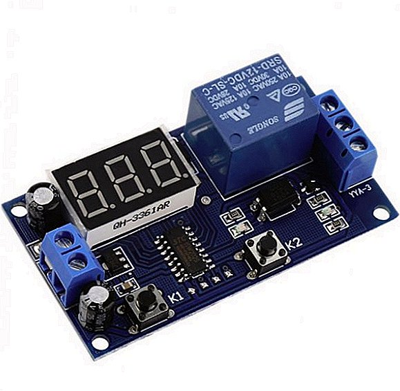
Creating a timer for an incubator based on one of these devices will not be difficult. Moreover, you don’t even have to take a soldering iron in your hands, since the range of industrially manufactured boards based on KR512PS10 is extremely wide, their functionality is diverse, and the ability to adjust time intervals covers a range from tenths of a second to 24 hours.  The finished boards are equipped with the necessary automation, which ensures fast and accurate setting of the “work” and “pause” modes. Thus, the manufacture of a timer for an incubator on a KR512PS10 microcircuit is reduced to the correct choice of board for the specific characteristics of a specific incubator.
Find out what the temperature should be in the incubator, as well as how to disinfect the incubator before laying eggs.
If you still need to change the operating time, you can do this by shorting the resistor R1.
For those who love and know how to solder, and also wants to assemble a similar device with his own hands, let us present one of the possible schemes with a list of electronic components and a trace of a printed circuit board.  The described timers are applicable for controlling the tray turning over in working with household incubators with periodical switching on of heating elements. In fact, they allow you to synchronize the movement of the tray with the heater on and off with cyclically repeating the entire process.
Other options
In addition to the considered options for basic circuits, there are many electronic components on which you can build a reliable and durable device - a timer.
Among them are:
- MC14536BCP;
- CD4536B (with modifications CD43 ***, CD41 ***);
- NE555 et al.
To date, some of these microcircuits have been discontinued and replaced with modern analogues (the electronic component manufacturing industry is not standing still).
All of them are distinguished by secondary parameters, an expanded range of supply voltages, thermal characteristics, etc., but at the same time they perform all the same tasks: turning the controlled electric circuit on and off according to a given program. 
The principle of setting the working intervals of the assembled board is the same:
- find and short circuit resistor "pause";
- set the desired diode blinking frequency by the “work” mode resistor;
- unlock the pause mode resistor and measure the exact running time;
- set the parameters of the divider;
- place the board in a protective case.
Making the tray flip timer, you need to understand that this is primarily a timer - a universal device, the scope of which is not limited solely to the task of turning the tray in an incubator.
Subsequently, having gained some experience, you will be able to provide similar devices and heating elements, a lighting and ventilation system, and later, after some modernization, use it as a basis for automatically feeding and feeding water to chickens.
Did you know? Many believe that the yolk in the egg is the germ of the future chicken, and the protein is the nutrient medium necessary for its development. However, in reality it is not. The chick begins to develop from the germinal disc, which in the fertilized egg looks like a small speck of light color in the yolk. The nestling feeds mainly on the yolk, but the protein is a source of water and useful minerals for the normal development for the embryo.
Among the alternatives, it should also be noted that the radio markets and specialized stores will offer you a huge selection from electronic components and circuit boards to ready-made timers for incubators.  The price of many types of finished automation may be even lower than the cost of self-assembly. The decision to take you. Thus, it is not difficult to make a timer yourself. With certain skills, the process does not take much time. As a result, you will get reliable automation for an incubator that you can trust.